New Guide: Build a NeoPixel Crystal Chandelier with Speed & Brightness Control

DIY crystal chandelier

Take a look at the latest guide from Erin St. Blaine: build a three tiered chandelier with hanging DIY paper-craft crystals that light up with pixels inside. Easily add your own custom animations using CircuitPython and the LED Animations Library. This guide takes animated lights a step further, adding a rotary encoder knob that controls the brightness or the animation speed of the pixels, and also acts as an on/off switch. From the guide:

Floating crystals and glowing lights are a match made in heaven. This project combines a wide variety of skills and tools into one lovely project. Make a gorgeous hanging lamp with sparkly beads, glowing crystals, live edge wood and of course, lots of NeoPixels.

My chandelier is unique, and designed to show my personal style. Since you, dear reader, have your very own unique style, this tutorial will focus on giving you the tools to design and create your own one-of-a-kind bespoke hanging lamp. This tutorial will provide source files and ideas, and give guidance on how the electronics fit together.

This tutorial will also get you started with customizing your own software animations. The sample code uses CircuitPython and the delightfully easy to use LED Animations Library by Kattni Rembor. This code gives you a framework that allows speed and brightness control using a rotary encoder knob, so you can adjust the lighting to suit any environment or mood.

See the full build tutorial here: https://learn.adafruit.com/neopixel-crystal-chandelier-with-circuitpython-animations-and-speed-control/overview

crystal chandelier

We can’t wait to see the creative lamp you build with NeoPixels and Circuit Python!

LLNL Researchers Use Laser Beam Shaping to Enhance Properties During Metal 3D Printing

Custom laser powder bed fusion test setup for producing single track samples in an argon flow and capturing high speed image data of the process.

From bioprinting blood vessels and using 3D printing to control reactive materials to 3D printing nanoporous gold and researching metal 3D printing flaws, the scientists at Lawrence Livermore National Laboratory (LLNL) are well known for their impressive work with 3D printing materials. Recently, a group of LLNL researchers explored the use of spatial laser modulation in enhancing the processability and properties of 3D printing metals. The team created a custom laser powder bed fusion (LPBF) test bed, which can produce single tracks of steel 316L under various conditions.

Top and transversal cross-sectional views of simulated melt-track formation by the Gaussian (a, b) and longitudinal elliptical (c, d) beams, where laser scanning occurs in the positive x-direction.

The alloys used most often for metal 3D printing, like 316L stainless steel, titanium alloys like Ti6Al4V, Inconel 718/625 superalloys, and aluminum alloys such as AlCuMgScSi, are more developed for standard manufacturing than they are for AM processing; reasons for this include unsuitable materials feedstocks, little control over local thermal histories that drive microstructure control, and deficient predictive capabilities due to limited data from in situ process monitoring.

In addition, while metal LPBF 3D printing has a lot of potential for a wide variety of applications, it lacks the degree of control that’s necessary to produce parts that can meet exacting, performance-driven criteria. In order to continue driving 3D printing from a rapid prototyping mindset to rapid manufacturing, it’s important to have in-depth knowledge of the AM process and the structures it can create. To do this, the LLNL researchers are working to develop a new science-based AM design strategy that can control thermal history by using tailored and simulation-driven light sources.

M.J. Matthews, T.T. Roehling, S.A. Khairallah, G. Guss, S.Q. Wu, M.F. Crumb, J.D. Roehling, and J.T. McKeown with LLNL recently published a paper, titled “Spatial modulation of laser sources for microstructural control of additively manufactured metals,” where they demonstrate how beam ellipticity can be used for microstructural control during LPBF 3D printing.

The abstract reads, “In this work, we explore spatial laser modulation to enhance the properties and processability of AM metals. Experiments are carried out with the goals of demonstrating control of the columnar-to-equiaxed transition, identify methods to reduce surface roughness, and extend processing windows for AM alloys. Results show that beam modulation provides site-specific microstructural control, and these results are interpreted using finite element modeling of the melt pool dynamics and thermal profiles.”

The team used simple beam shaping optical elements which could, in theory, be implemented on a commercial AM system someday.

“Thus, through engineering of the thermal gradients with such optics, it may be possible to control equiaxed or columnar grains at specified locations by modulating beam shape during a build,” the researchers wrote.

Conceptual framework for tuning material properties in AM using tailored light sources like shaped beams.

316L stainless steel powder from Concept Laser on 316L stainless steel substrates was used during the single-track laser melting experiments. In their LPBF testbed, the team used a 50 mm FL lens to make rays of light from of a 600 W fiber laser parallel. Using LLNL’s ALE3D numerical simulation software tool, the researchers modeled the actual particle size distribution and random particle packing, before using a laser ray tracing algorithm to simulate laser interaction with the actual powder bed.

“The three-dimensional model was addressed using a hybrid finite element and finite volume formulation on an unstructured grid,” the researchers wrote. Simulations were run using each beam shape at Size S for P = 550 W. To conserve computational time, the scan velocity was set at 1800 mm/s, resulting in an energy density of 61 J/mm3. This energy density is slightly lower than the minimum value used in the experiments (80 J/mm3).”

Microstructure cross-sections as a function of beam shape: (a) Gaussian, (b) longitudinal elliptical and (c) transverse elliptical.

Using LLNL’s ALE3D code to model laser-model interactions made it possible to investigate beam shape effects on track macro- and microstructures. The researchers determined that “equiaxed solidification was favored at lower laser powers,” independently of beam ellipticity or size; this was observed particularly when substrate penetration by the melt was poor or even absent.

The concentration of columnar grains generally increases when the power and scan speed goes up as well, and the parameter space, “over which equiaxed or mixed equiaxed-columnar microstructures” were made,” was larger for elliptical beams than it was for Gaussian ones. This shows that it it is possible to achieve site-specific microstructural control by varying the beam ellipticity. Additionally, even more complex microstructures are possible with full builds that use alternate beam shapes.

“The effects of Gaussian and elliptical laser intensity profiles on single-track microstructures were investigated. Beam ellipticity demonstrated a strong effect on solidification microstructure. The elliptical intensity profiles produced equiaxed or mixed equiaxed-columnar grains over a much larger parameter space than the circular profiles when conduction-mode laser heating occurred. This indicates that grain morphology can be tailored by varying beam intensity spatial profile while maintaining constant laser power and scan speed,” the researchers concluded.

Because the research showed that it’s possible to locally tune microstructures, users can now engineer site-specific properties right into 3D printed parts, which ultimately means more design flexibility.

Discuss this research and other 3D printing topics at 3DPrintBoard.com or share your thoughts below. 

Researchers from S2A Lab Experimenting with Remote 3D Printing Control

Late last year, we learned that researchers with the Smart and Sustainable Automation Research Lab (S2A Lab) at the University of Michigan College of Engineering had been working to develop an algorithm that would double the speed of desktop 3D printers. It works by using Filtered B-Spline (FBS) algorithms to adjust 3D printer control and mitigate unwanted vibrations while the print speed goes up. Earlier this week, we received an update on the team’s vibration compensation algorithm from Chinedum Okwudire, PhD, an associate professor of mechanical engineering at the university and the director of S2A Lab.

“Over the past year we have been working to integrate our vibration compensation algorithm into Marlin and release it open-source to the 3D printng community. But we have not succeeded because of the low computational power and memory on the ATMega2560 microcontroller which cannot support our algorithm,” Professor Okwudire told 3DPrint.com. “We are now looking into releasing it open-source on firmware that run on more powerful microcontrollers. More updates on this to follow as we make more progress.”

CAD model of XYZ Calibration Cube commonly used for determining acceptable acceleration and jerk speed limits of desktop 3D printers.

But the innovative vibration compensation algorithm isn’t the only thing the researchers in the S2A Lab have been working on lately.

“In the meantime, we have been experimenting with a new way of controlling 3D printers, where stepper motor commands (and other low-level control commands) are generated in the Cloud, rather than on a microcontroller,” Professor Okwudire explained to us. “The idea is not too different from how video streaming works, and is a refined version of how OctoPrint, Astroprint and 3DPrinterOS work. It gives Wi-Fi enabled 3D printers access to advanced algorithms like ours, running on the Cloud, without need for very powerful microcontrollers. Our initial results have been very encouraging. We were able to compensate the vibration of a Lulzbot Taz 6 3D printer situated in Michigan from cloud-based controllers in South Carolina and in Australia without much problems, hence slashing printing time by up 54% compared to using Marlin. Details of this work are published in the special issue on Innovations in 3D Printing of the open-access journal Inventions.”

The team published the details of their work in a paper, titled “Low-Level Control of 3D Printers from the Cloud: A Step toward 3D Printer Control as a Service,” in a special issue of open access journal Inventions all about 3D printing innovations; co-authors include Professor Okwudire, Sharankumar Huggi, Sagar Supe, Chengyang Huang, and Bowen Zeng.

Overview of setup for experiments.

The abstract reads, “Control as a Service (CaaS) is an emerging paradigm where low-level control of a device is moved from a local controller to the Cloud, and provided to the device as an on-demand service. Among its many benefits, CaaS gives the device access to advanced control algorithms which may not be executable on a local controller due to computational limitations. As a step toward 3D printer CaaS, this paper demonstrates the control of a 3D printer by streaming low-level stepper motor commands (as opposed to high-level G-codes) directly from the Cloud to the printer. The printer is located at the University of Michigan, Ann Arbor, while its stepper motor commands are calculated using an advanced motion control algorithm running on Google Cloud computers in South Carolina and Australia. The stepper motor commands are sent over the internet using the user datagram protocol (UDP) and buffered to mitigate transmission delays; checks are included to ensure accuracy and completeness of the transmitted data. All but one part printed using the cloud-based controller in both locations were hitch free (i.e., no pauses due to excessive transmission delays). Moreover, using the cloud-based controller, the parts printed up to 54% faster than using a standard local controller, without loss of accuracy.”

Control as a Service (CaaS) is just one of several examples, such as cloud robotics and cloud manufacturing, of paradigms inspired by, and built on the shoulders of, cloud computing and other service-oriented architectures (SOA). It works like this: a device’s low-level control functionalities are moved out of a local controller to the Cloud, where they can then be accessed on-demand remotely. Multiple 3D printing services rely on SOAs and cloud computing, and the trend of controlling 3D printers remotely through a web-based wireless host platform, such as OctoPrint, 3DPrinterOS, and Astroprint, continues to grow.

But, these types of platforms send G-codes, or the equivalent, from the Cloud to the 3D printer while at the same time assigning lower level computations to a microcontroller. So these don’t offer the same kind of CaaS that the S2A Lab is working to develop.

“3D printers are an excellent case study for advancing CaaS, especially since many of them (particularly those of the desktop kind) have very limited computational resources on their local controllers,” the researchers wrote. “The control performance of desktop 3D printers could be significantly improved at low cost via cloud-based control algorithms provisioned through CaaS.”

The researchers used a Lulzbot Taz 6 3D printer with dual extruders for their experiments, though mentioned in the paper that industrial 3D printers could also stand to benefit from this kind of advanced control algorithm.

“Therefore, this paper presents preliminary work on low-level motion control of a desktop 3D printer from the Cloud, as a first step towards in-depth research into 3D printer CaaS (3DPCaaS). It not only shows that low-level control of 3D printers from the Cloud is feasible, but also demonstrates huge improvements in 3D printing speed and accuracy that can be achieved using an advanced cloud-based motion controller over a standard local controller,” the researchers wrote.

Prints of Medieval Castle using: (a) local controller (Marlin); (b) cloud-based controller in South Carolina; and (c) cloud-based controller in Australia. The portions of the prints highlighted in dashed rectangles failed (broke off) during printing due to delicate support structures.

The S2A Lab set up a website as a gathering place for people who want to continue researching the idea, and testing 3DPCaaS on their own 3D printers.

“This work is still very experimental but it has shown great promise,” Professor Okwudire told 3DPrint.com. “It may just be the next big thing in 3D printer control, where printers can gain on-demand access to powerful algorithms that boost their performance without need to upgrade to very powerful microcontrollers. What we picture is an OctoPrint-like platform where people can upload G-Codes and remote control their printers with the help of advanced algorithms like ours running from the Cloud.”

Discuss this and other 3D printing topics at 3DPrintBoard.com or share your thoughts below.

The 3D Printing Octagon  

A few years ago I started to think of 3D printing as a triangle where you had to control for each part of the delta: software, machines, and materials. I’ve now come to realize that it is more complex still. In order to get true repeatability, reliability and throughput in high-quality parts we have to from concept to customer consider the most significant influences on 3D printing.  We have to each of us, whether we be users, OEMs, manufacturers have to look at 3D printing holistically, and take into account how our inputs affect all others. Only by controlling for all sides of the 3D Printing Octagon can we ultimately succeed in 3D printing parts reliably and repeatably at scale.

People have been trying to reduce the influence of variables on 3D printed parts since the technology began. But, initially, it was one OEM who made the machine, sold the materials and made the software (or at least influenced these things). Companies like Stratasys and 3D Systems could coordinate all of the settings and variables to come up with coherent 3D prints. Their level of control meant that parts came out the right way every time. The current 3D printing landscape consists of this Closed way of doing things but also an Open Ecosystem. And let’s be frank guys, the Open Ecosystem is currently a mess. Everyone is just winging it. People are building systems willy-nilly without much a thought to the importance of software. A lot of OEMs have very little understanding of firmware and the effects of that on prints. Materials companies just throw stuff over the hedge with settings such as between 200 and 230 C? You’re joking right, would that work if I were baking a cake? Part of that problem is due to run to run differences on machines. Often machines can be found to have temperature differences at the nozzle of 10 to 15 degrees. So the temperature that you’re printing at is probably not the temperature you’re actually printing at. A knock on effect of this is that a lot of 3D printing research is junk because it doesn’t correct for these temperature differences. There is variability also in the torque of the mostly totally crappy stepper motors we use as well. Open printers have huge influences from airflow, ambient temperature, and humidity. Often there are considerable temperature fluctuations in a build chamber during a build. We all just random walkaly try to solve the bed adhesion issues as if it were second grade and we’re playing with glue-sticks. There are inconsistencies in procedures as well. Settings on the printer are dealt with if they’re some kind of dadaist art form with everyone semi-randomly changing retraction, speeds and extrusion power. Gcode and the way the nozzle actually builds up a part has effects which are not addressed. Design for 3D printing is something that is being made up as we go along but is hampered because we make up new terms for everything. We can’t even agree to all use Material Extrusion, FDM, FFF or whatever to describe the different technologies. We don’t have a universal accuracy measurement or a way to test 3D printer performance. Most dogbones are printed in vain due to inconsistencies in testing methodology. Kids, it’s time to put down the screwdrivers for a moment and work together.

1. Standardization & Testing. We need to adopt the same terminology, procedures, tests, and standards if we are to advance. I know this is boring, but it is also essential. If we don’t do this, then there is no way through which we can collectively advance the industry. Furthermore, a lot of inefficiencies will be created while everyone tries to build their platform. We can opt for, or a “chaotic everyone do their own thing industry” if we want, but we would get to better parts quicker by working together. You see, you may think you’re competing against one another, but this is not true. What we’re competing with is injection molding, clay, welding or any other manufacturing technology. We have to make 3D printing more viable for more things. That way we all profit. The more things we can make reliably; the more valuable and desirable our machines, materials, and software will be. I’ve said this before but you are not Boeing, and the other guy is not Airbus. There are 7 billion people on this planet that do not use 3D printing, the ones that do for business or at home are essentially a rounding error. We can perhaps now make only around 2% of all the things in the world. It is by activating more people on 3D printing and by making more prints possible that we all advance. Meanwhile a lot of you hawkeyed look at the other guy like we’re some mature no-growth industry. Stop with this nonsense, but rather help us make us the answer to all the things that do not exist yet.

After we, hopefully, standardize our nomenclature and testing we should come to grips with the other sides of the 3D Printing octagon. If we want to produce parts reliably, we will need to realize that there are seven sides to this problem and that they all have to be understood and controlled for 3D printing to work well. If we industrialize, we will have to control for and master the entire octagon. Lack of understanding of one or more elements of the octagon means that we will screw up at one point. This is all well and dandy for your Yoda head but not for my 3D printed heart. This is the future guys, and the future sucks because it will have a lot of statistics in it, graphs and clipboards.

2. Machine & Slicer Settings The machine settings influence how quickly a part is printed at what speed the head moves and at what temperature the nozzle extrudes. Settings have direct effects on wall slip, pressure and the voxel as it is being built. Individual settings such as retraction work in concert with and have significant feedback loops with other parameters such as speed, feeder setting, feeder speed, etc. These settings also cannot be universally applied and do not have consistent effects. E.g., differences in filament roundness can interfere with consistent extrusion and mask optimal extrusion speeds or differences in filament surface finish can cause different optimal feeder settings. Settings are often user tweaked in isolation, and the user often feels as if they are “learning how to 3D print” whereas in actuality they are continually compensating for other misunderstood differences in environment, material or design. Incorrect and inconsistent use of settings leads to many print failures and is the chief reason why 3D printing is advancing slower than it should on the desktop. It’s as if we’re all trying to bake cakes, but no one ever writes down a recipe or even defines what boiling or icing means. In this case, I’ve lumped together slicer and machine settings because they work in concert and are both open to user input often to that user’s detriment.

3. Machine & Environment  By machine we mean here the actual positioning, movement, and print process that the machine parts are doing at any one time. In this sense lack of calibration, calibration procedure or run to run differences inhibit precision. Through machine, we also mean the internal surfaces in the machine, especially where melt occurs. The pressure in the nozzle, as well as the surfaces of these critical pathways, are little understood. We will need to grasp these effects much more precisely. Understanding settings are also in and of themselves useless if the machine inconsistently acts upon these settings.

We must control the machine in order for it to build parts. We must also manage the environment. At one point, hopefully, all printers will be closed, and we’ll breathe in fewer fumes and get better print results. We have to control airflows, laminar flow, heat, ambient temperature and humidity if we are to print consistently. Right now people are spoiling their datasets by printing near windows or with heat changes in their buildings. We need to bring down the excessive number of variables and their effects significantly.  

4. Material Material roundness and diameter has significant effects on nozzle pressures and misprints. The temperature that materials have to be extruded at to get optimal layer adhesion is often also not precisely understood or communicated. There are also many material dependent settings and differences. Some materials require fans to be at 100% some print better when they are off. The interplay between materials and settings with the complex feedback loops occurring there are not understood by industry. Often much instruction and expounding on optimal settings are not much better than guesswork. The correct applications of the right material for the correct part is also not communicated. Polymer companies toss resin pellets at extrusion companies that gleefully catch this manna from heaven before extruding it, rolling it up and frisbeeing that at an OEM. OEM’s copy paste some info and pass it on to users. No one speaks the same language, and no one understands each other. Additives, grades, and polymers themselves can have massive effects. Many users are not even aware that colorants mean that different PLA’s from the same vendor print best at different nozzle temperatures.

Through this five hundred million dollar whispering word game, the user is left with some marketing slogans and imprecise guidance on when to use a material and how to print it. OEMs and retailers want better printability, and by putting them in the driving seat, we’ve set the “spreadability” of butter as the main priority rather than its taste. Printability is when a machine manufacturer asks you to cover up their machine’s failings through polymer chemistry or additives. Printability is a lie. A 3D printer manufacturer telling us what materials to print and how is like an arsonist advising the fire department. I do not in the slightest doubt that there is real affinity and interest, but in the final analysis, our shared goal does diverge. You want a thing that makes your machine look good, and I want a thing that gives me the best parts and best properties.

5. Operator & Process Touched on above, the operator is mostly a creature of random habit. Part artist part scientist excelling at neither we blunder through misprint after misprint. Look I also thoroughly enjoyed the exploration and astronaut feeling of 3D printing initially. But, could we now make it humdrum and predictable? And Astronauts become astronauts through learning and stay alive through a process. We need the best processes, and we need these mapped and explained well.

One of the most prominent failure modes in desktop 3D printing is layer adhesion issues with your first layer. Often the cause of this is greasy fingers on the build platform. Clean the platform, and many first layer issues disappear. 3D printing would be much better if we all knew the best way to do certain things. Many misprints are also due to incorrect storage of PLA and moisture on it. There have to be processes for these kinds of seemingly ancillary but crucial things as well. The rote concentration and effort of processes correctly implemented by a knowledgeable operator working systematically will be tedious but will reduce failure rates for all of us.

6. FIle The STL needs to die in a fire, this much is certain. We need to have one good file type that can describe densities, colors, patterns and every bit of information in the voxel at every location. We also have to find ways of going from CAD directly to movement on the machine while also finding better ways to describe circles, triangles, and parts. A lot of CAD software changes the way your file works and a lot of information that we want in the file such as where it is from and how it can become parametric and what materials work how is absent. I’ve previously been a proponent of sDNA which essentially is an idea whereby an XML file format contains not only a description of the thing but the thing in all of its permutations in all of the available materials with the relevant settings and attribution and use information. We will need this eventually, and the sooner we get it, the better.

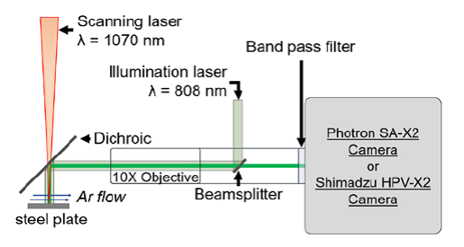
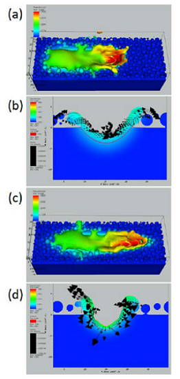
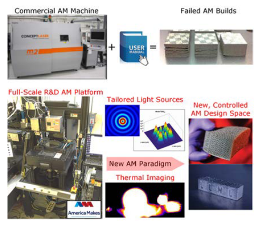
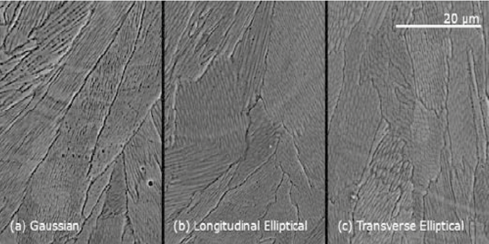
7. Toolpath, Melt Pool & Infill Toolpaths are not intelligent and can be optimized. Much more efficient ways to draw objects can be found. More research needs to be done as to how the nozzle moves and how this coupled with extrusion speed, wall slip effects, and nozzle diameter makes your print. If the laser would build a part with a different spot size or melt pool, then the consequences are enormous on the part. We need to be able to control where crystallization occurs (when and if it is intended to happen) and we need more control over the actual placement/melting in place of material. Once we can do that, then we can genuinely consider each print a unique material made for one application and can control for and optimize the qualities of that part at every voxel. Then we can also dynamically optimize infill patterns, shapes and make them dynamic as well. We could then design the sand, shape the mortar and use both to build a house by letting us determine the right properties at each voxel, also at each 3D infill space and also of the part as a whole through the modification of these three in concert.

8. Design Stuck in our Voronoi ways we’ll hopefully look back at this as a quaint time of salt of the earth people. Like how we now look at times when only truckers wore trucker hats and New York didn’t look like a German U-Boot crashed off of Greenpoint. Form follows function is such a universally held truism in design that few actually practice it. But, by starting from the utility of a thing, how long it needs to exist and what it needs to do we can then go to a functional shape. Using FEA and other techniques more designers and engineers will start to make objects that are made for a purpose. We will need to get our heads around optimal weight saving techniques, how to integrate multiple functionalities in one object, how to reduce part count, how to iterate and test designs. We will have to look again at textures, topology optimization and how this works in conjunction with the possible and desirable. Design and engineering from 3D printing will be many iterations, many failures agile engineering affair. If this is done in conjunction with those above to control for the 3D Printer Octagon then we will have a 3D printed world. Have at it.