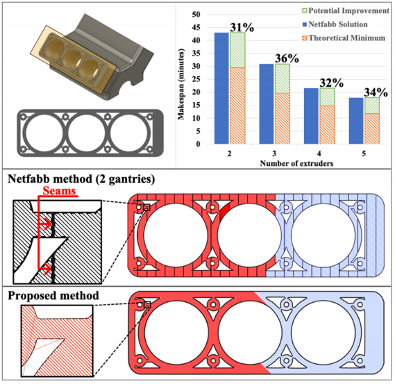
French researchers from Université de Lorraine assess 3D printing techniques and recycling feedstocks, detailing their study in the recently published ‘Mechanical Properties of Direct Waste Printing of Polylactic Acid with Universal Pellets Extruder: Comparison to Fused Filament Fabrication on Open-Source Desktop Three-Dimensional Printers.’
While FDM (FFF) 3D printing has become highly accessible and affordable to users around the world, in this study the researchers also focus on the use of fused granular fabrication (FGF). Exploring the potential for continued ‘greening of distributed recycling,’ the researchers assess both FDM and FGF techniques for the desktop, experimenting with the following recycling filaments:
- Commercial filament
- Pellets
- Distributed filament
- Distributed pellets
- Waste
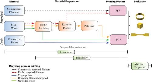
Global framework of the experimentation. FFF, fused filament fabrication; FGF, fused granular fabrication; PLA, polylactic acid. Color images are available online.
A large part of the assessment included comprehensive studying of the granules (granulometry) used due to concerns regarding quality of reproducibility in the samples. Cost was substantially reduced, with material costing less than 1 €/kg – in comparison with 20 €/kg for commercial recycled filament. Better affordability coupled with quality in performance offers obvious benefit to users, with the potential for promoting a circular economy and efficient recycling.
“Due to the introduction of the open-source self-replicating rapid prototyper (RepRap), the dominant technology of 3D printing is fused filament fabrication (FFF) using polylactic acid (PLA),” stated the researchers. “Various forms of filament extrusion systems have proven effective at recycling PLA. However, PLA degrades with each cycle through the print/grind/extrude to filament/print loop.”
“This issue can be partially controlled by adding virgin PLA to recycled PLA, coatings, or carbon fiber reinforcement.”
By effectively eliminating the need to use filament and move directly to recycling waste, the researchers expect numerous benefits to continue emerging: reduced use of energy, faster production time, and less resources expending in making filament.
The following types of PLA were used:
- Virgin, commercial PLA 4043D from NatureWorks (pellet form)
- Recycled PLA filament from Formfutura for FFF printing
- Recycled PLA filament produced in situ in ‘fablab conditions,’ meant for FFF printing
- Pelletized feedstock for FGF
- Shredded PLA from 3D printed waste, for FGF
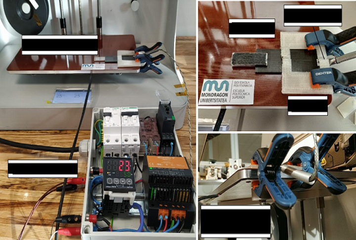
In experimenting with the FFF system, the researchers used a Prusa i3 running Marlin firmware v1.1.9.
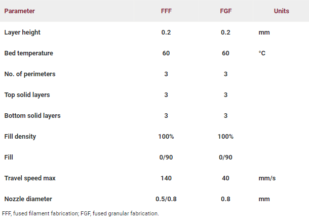
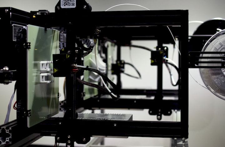
The FGF printer comprised a pellet extruder kit39 adapted to a commercial FFF printer (Créality CR-10S pro48) machine using a Marlin firmware v1.1.19. The pellet extrusion kit uses an auger screw with a diameter, cartridge heater –, and nozzle diameter that mixes and extrudes the melted material. The hot end of the FFF printer was adapted by replacing the pellet extruder prototype as shown in Figure 2. After the mechanical assembly was made, the first experimental tests were carried out to adapt the machine to the new parts and calibrate the formation of an extruded filament by using virgin PLA pellets. The extrusion factor was changed to calibrate the rotation of the screw extruder.
The FGF printer consisted of a pellet extruder attached to a Créality CR-10S pro 3D printer using Marlin firmware v1.1.19.

(a) FFF and (b) FGF printers used in the experimentation. Color images are available online.
Eight test samples were weighed and measured, and then evaluated for the following:
- Tensile strength
- Strain
- Elastic modulus

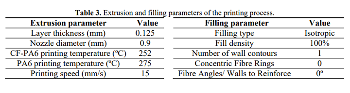
Printability of shredded PLA materials. Color images are available online.
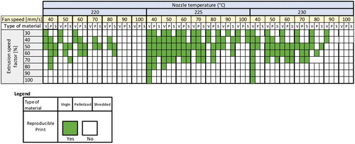
Printability of shredded PLA materials. Color images are available online.
“Regarding the economic aspect, using the FGF printer with virgin PLA pellets, there is a 65% reduction in printing cost per kilogram and a shorter production time compared with recycled commercial filaments, which is a non-negligible option. The results show that the main cost in 3D FFF printing is in the acquisition of filaments. However, the acquisition of recycled material filaments reduces the cost in relation to the acquisition of virgin material filaments, providing a reduction in the use of virgin raw material in 3D printing,” concluded the researchers.
“Opportunities arise in the possibility of using other types of recycled waste, including flexible and composite (plastic/plastic) materials as has been done on larger systems. Also, main factors such as polymer viscosity, which need to be controlled in the FGF process, are needed.”
Undoubtedly recycling will continue to be an ongoing theme in the 3D printing industry, with previous studies reflecting the state of recycling, solvent recycling, and circular chemical recycling. What do you think of this news? Let us know your thoughts! Join the discussion of this and other 3D printing topics at 3DPrintBoard.com.
[Source / Images: ‘Mechanical Properties of Direct Waste Printing of Polylactic Acid with Universal Pellets Extruder: Comparison to Fused Filament Fabrication on Open-Source Desktop Three-Dimensional Printers’]
The post Université de Lorraine: Direct Waste Printing with PLA Pellets Versus FDM 3D Printing appeared first on 3DPrint.com | The Voice of 3D Printing / Additive Manufacturing.

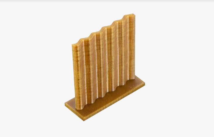
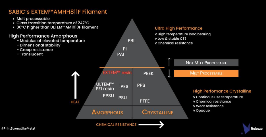
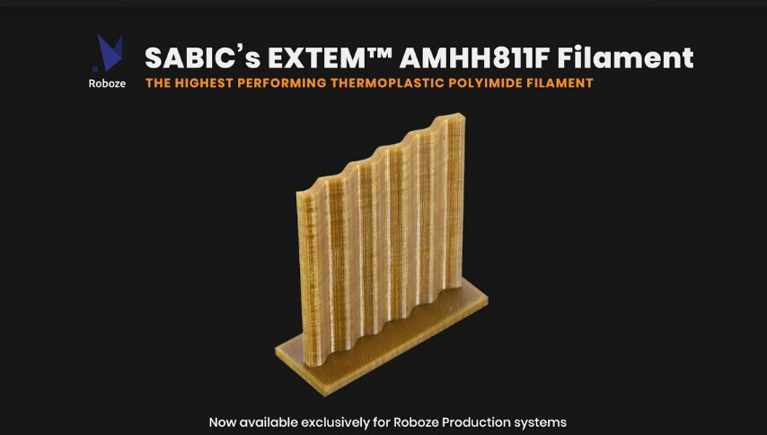
 AMHH811F, meant to offer superior performance in parts for industrial users engaged in FFF 3D printing.