
3D Sierra Leone, a dutch nonprofit organization, is providing customized 3D printed prostheses to patients in the West African country, with the support of SHINING 3D, a Hangzhou-headquartered 3D scanner and printer manufacturer. 3D Sierra Leone is dedicated to improving the lives of people in Sierra Leone that undergo amputations but are without access to […]
Prize winning space-time research expands design for additive manufacturing
Researchers from the Delft University of Technology (TU Delft) in the Netherlands have developed a method to concurrently optimize 3D printed structures and the fabrication sequence that creates them, specifically in the wire arc additive manufacturing process (WAAM). The method comprises a topology optimization formulation capable of simultaneously enhancing the density field for defining the […]
Collaborative Research Team Develops Density-Graded Structure for Extrusion 3D Printing of Functionally Graded Materials
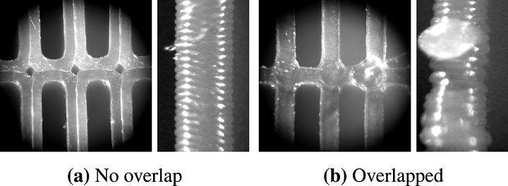
Microscopic photos of top and side views of printing results with a 0.38 mm wide extrusion path: (a) without versus (b) with overlapping by 0.36 mm respectively. Overlapping extrusion paths exhibit over-extrusion of material at the overlapping region, which results in unwanted blobs on the surface of the print.
Plenty of research has been completed in regards to FDM (extrusion) 3D printing, such as how to improve part quality and how to reliably fabricate functionally graded materials (FGM). The latter is what a collaborative team of researchers from Ultimaker, the Delft University of Technology (TU Delft), and the Chinese University of Hong Kong are focusing on in their new research project.
The team – made up of researchers Tim Kuipers, Jun Wu Charlie, and C.L. Wang – recently published a paper, titled “CrossFill: Foam Structures with Graded Density for Continuous Material Extrusion,” which will be presented at this year’s Symposium for Solid and Physical Modeling.
“In our latest paper we present a type of microstructure which can be printed using continuous extrusion so that we can generate infill structures which follow a user specified density field to be printed reliably by standard desktop FDM printers,” Kuipers, a Software Engineer and Researcher for Ultimaker, wrote in an email.
“This is the first algorithm in the world which is able to generate spatially graded microstructures while adhering to continuous extrusion in order to ensure printing reliability.”
 Because 3D printing offers such flexible fabrication, many people want to design structures with spatially graded material properties. But, it’s hard to achieve good print quality when using FDM technology to 3D print FGM, since these sorts of infill structures feature complex geometry. In terms of making foam structures with graded density using FDM, the researchers knew they needed to develop a method to generate “infill structures according to a user-specific density distribution.”
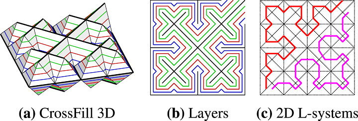
The abstract reads, “In this paper, we propose a new type of density graded structure that is particularly designed for 3D printing systems based on filament extrusion. In order to ensure high-quality fabrication results, extrusion-based 3D printing requires not only that the structures are self-supporting, but also that extrusion toolpaths are continuous and free of self-overlap. The structure proposed in this paper, called CrossFill, complies with these requirements. In particular, CrossFill is a self-supporting foam structure, for which each layer is fabricated by a single, continuous and overlap-free path of material extrusion. Our method for generating CrossFill is based on a space-filling surface that employs spatially varying subdivision levels. Dithering of the subdivision levels is performed to accurately reproduce a prescribed density distribution.”
![]() Their method – a novel type of FDM printable foam structure – offers a way to refine the structure to match a prescribed density distribution, and provides a novel self-supporting, space-filling surface to support spatially graded density, as well as an algorithm that can merge an infill structure’s toolpath with the model’s boundary for continuity. This space-filling infill surface is called CrossFill, as the toolpath resembles crosses.
Their method – a novel type of FDM printable foam structure – offers a way to refine the structure to match a prescribed density distribution, and provides a novel self-supporting, space-filling surface to support spatially graded density, as well as an algorithm that can merge an infill structure’s toolpath with the model’s boundary for continuity. This space-filling infill surface is called CrossFill, as the toolpath resembles crosses.
“Each layer of CrossFill is a space-filling curve that can be continuously extruded along a single overlap-free toolpath,” the researchers wrote. “The space-filling surface consists of surface patches which are embedded in prism-shaped cells, which can be adaptively subdivided to match the user-specified density distribution. The adaptive subdivision level results in graded mechanical properties throughout the foam structure. Our method consists of a step to determine a lower bound for the subdivision levels at each location and a dithering step to refine the local average densities, so that we can generate CrossFill that closely matches the required density distribution. A simple and effective algorithm is developed to merge a space-filling curve of CrossFill of a layer into the closed polygonal areas sliced from the input model. Physical printing tests have been conducted to verify the performance of the CrossFill structures.”
The researchers say that the user prescribes density distribution, and can use CrossFill and its space-filling surfaces, with continuous cross sections, to “reliably reproduce the distribution using extrusion-based printing.” CrossFill surfaces are built by using subdivision rules on prism-shaped cells, each of which contains a surface patch that’s “sliced into a line segment on each layer to be a segment” of the toolpath, which will be made with a constant width; cell size determines the density.
“By adaptively applying the subdivision rules to the prism cells, we create a subdivision structure of cells with a density distribution that closely matches a user-specified input,” the team wrote. “Continuity of the space-filling surface across adjacent cells with different subdivision levels – both horizontally and vertically – is ensured by the subdivision rules and by post-processing of the surface patches in neighboring cells.”
The subdivision system distinguishes an H-prism, which is built by cutting a cube in half vertically along a diagonal of the horizontal faces, and a Q-prism, generated by spitting a cube into quarters along the faces’ diagonals. To learn more about this system and the team’s algorithms, check out the paper in its entirety.
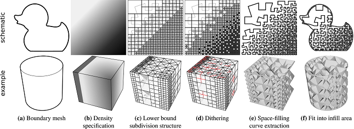
Schematic overview of our method. The top row shows a 2D analogue of our method for clear visualization. The prism-shaped cells in the bottom row are visualized as semi-opaque solids to keep the visualization uncluttered. Red lines in the bottom row highlight the local subdivisions performed in the dithering phase.
The researchers also explained the method’s toolpath generation in their paper, starting with how to slice the infill structure into a continuous 2D polygonal curve for each layer of the object, which is followed by fitting a layer’s curve “into the region of an input 3D model.”
Experiments measuring features like accuracy, computation time, and elastic behavior were completed on an Intel Core i7-7500U CPU @ 2.70 GHz, using test structures 3D printed out of white TPU 95A on Ultimaker 3 systems with the default Cura 4.0 profile of 0.1 mm layer thickness. The team also discussed various applications for CrossFill, such as imaging phantoms for the medical field or cushions and packaging.
“The study of experimental tests shows that CrossFill acts very much like a foam although future work needs to be conducted to further explore the mapping between density and other material properties,” the researchers concluded. “Another line of research is to further enhance the dithering technique, e.g. changing the weighing scheme of error diffusion.”
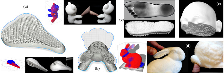
CrossFill applications. (a) Bicycle saddle with a density specification. A weight of 33 N is added on various locations to show the different response of different density infill. (b) Teddy bear with a density specification. (c) Shoe sole with densities based on a pressure map of a foot. (d) Stanford bunny painted with a density specification. (e) Medical phantom with an example density distribution for calibrating an MRI scanning procedure.
The team’s open source implementation is available here on GitHub. To learn more, check out their video below:
Discuss this story, and other 3D printing topics, at 3DPrintBoard.com or share your thoughts below.
TU Delft: Researchers 3D Printing Minimal Surface Structures Inspired by Origami
Although Japan is famous for their creations in origami, the craft is appreciated around the world, and recently by TU Delft researchers in the Netherlands who sought to understand more about folding mechanisms for complex efficient structures. Their findings are fully outlined in ‘Hyperbolic origami-inspired folding of triply periodic minimal surface structures,’ by Sebastien J.P. Callens, Nazlı Tümer, and Amir A. Zadpoor.
The Dutch researchers point out at the beginning of their study that geometries from triply periodic minimal surfaces—those that locally minimize an area, with vanishing mean curvatures present—have received a great amount of attention lately due to their potential for:
- High yield stress
- Low elastic modulus
- High fatigue resistance
- Bone-mimicking transport properties
And while TPMS structures are found to be ‘ideal for bone substitutes,’ the researchers explain that they are also suitable for creating a variety of structures that may be photonic, architected, or porous. They see obstacles in creating cellular structures, however, that can only be 3D printed in the form of lattices and are ‘incompatible with the planar functionality-inducing processes.’ As a result, the point of their research is to reduce constraints, while encouraging folding mechanisms, and innovating with new structures via sheet stretching. The authors also tweak the title of this new form of production from origami to origomu, since they are folding rubber instead of paper sheets—with ‘gomu’ meaning rubber.
Minimal material programming is required, and complex porous structures can be created this novel folding method:
“The rationale behind our approach consists of realizing curved minimal surface patches from a flat state, by combining rigid foldable frames with pre-strained elastomer sheets. Multiple of these foldable patches could then be connected together in a net and used as building blocks to fold a myriad of 3D TPMS-based architectures, ranging from single unit cells to larger assemblies consisting of multiple unit cells and 3D stackable minimal surface layers,” state the authors.
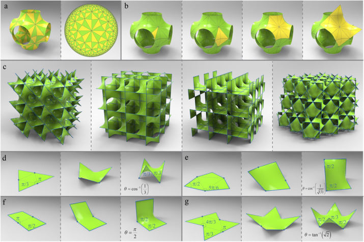
Geometry of TPMS and patch folding. (a) A translational P unit cell decorated with the hyperbolic *246 tiling of the fundamental asymmetrical patch. (b) Alternative patches to tile the P surface, shown together with the conventional unit cell. (c) The four TPMS considered here. From left to right: P, D, CLP, and C(P) surface. (d) Folding kinematics for the straight-edged skew polygonal patches of the P, D, CLP, and C(P) surfaces, respectively.
The concept of creating a TPMS structure in a saddle-shaped 3D puzzle form is the focus of the research, with their work using surfaces tiled by ‘straight-edged skew polygonal patches (homeomorphic to a disk).’
“A necessary (but not sufficient) condition therefore is the existence of embedded straight lines in the TPMS, which are axes of two-fold rotation and form the “linear skeletal net” of the surface,” state the researchers.
Polygonal patches are flattened with hinges attaches to boundary frame vertices, with edge lengths constant. This type of engineering allows for continuous folding of the frame to a flat polygon.
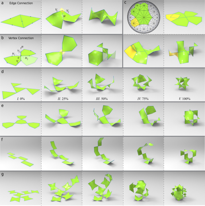
Connecting patches. (a) The edge-connection of two P patches. (b) The vertex-connection of two D patches. A transparent patch indicates a patch that fits in between two vertex-connected patches. (c) When trying to conform the hyperbolic (6,4) tiling of the D surface to the flat plane, one frequently encounters overlaps in the 2D net. (d–g) The folding of TPMS unit cells consisting of vertex-connected patches.
The patches can be connected to form more substantial minimal surfaces, resulting in a foldable 2D net, which then results in a 3D portion of the TPMS. Taking that one step further, the nets can continue to be connected, making even larger assemblies. Frames were 3D printed on an Ultimaker 2+ FDM printer, using PLA, with a 0.25 mm diameter nozzle and a layer thickness of 0.6 mm.
“We physically realized our self-folding minimal surface structures by attaching stretched elastomer sheets to 3D printed foldable frames,” said the researchers. “Upon release, the strain energy in the sheets causes the flat polygonal frame to self-fold into the desired skew polygonal configuration, and the sheet spanning the frame adopts an energy-minimizing saddle-shaped geometry, approximating the minimal surface.”
For this study, the authors narrowed their focus to four different TPMS types, but other minimal surfaces could be constructed if desired; in fact, they predict that a variety of different morphologies could be created.
“In this work, we focused on sheet-based structures, but beam-based lattices derived from the boundary frames could also be folded,” concluded the researchers. “Finally, our approach is not strictly bound by a specific length scale, meaning that it could also inspire the self-folding of architectural-scale tensile structures, nor is it limited to specific constituent materials, as long as a sufficient area distortion of the sheet surfaces and the rigidity of the boundary frames can be obtained.”
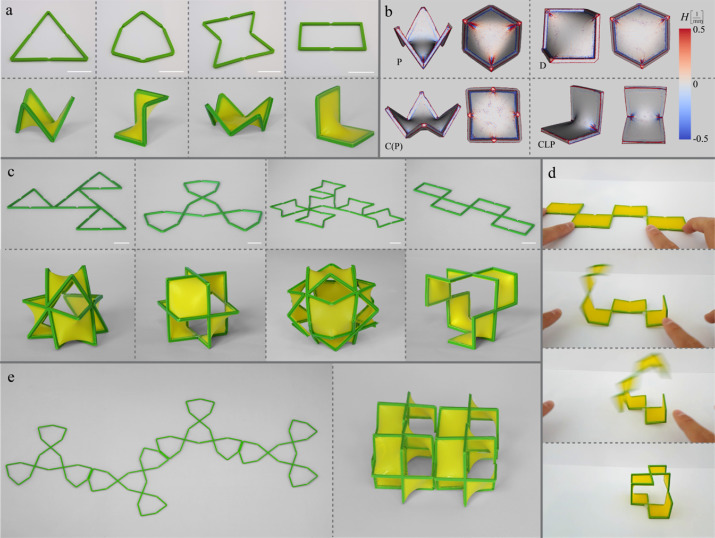
Self-folded physical models. (a) 3D-printed foldable frames for the four patch types in flat (top row) and folded (bottom row) configurations after the stretched latex sheets have been attached. (b) The mean curvature estimated using the 3D reconstructions of the four patch types obtained from micro-computed tomography data. (c) 3D-printed foldable TPMS unit cells in the flat (top row) and folded (bottom row) configurations. (d) The self-folding of the CLP unit cell through the pre-tension present in the latex sheet. (e) An assembly of four D unit cells in the flat (left) and folded (right) configurations. All scale bars are 20 mm.
Origami is an Asian craft so ancient that no one is sure whether it began in China or Japan, but Japanese artists have certainly made it their own over time. And because so many creative and scientific endeavors revolve around the creation of complex geometries and structures, origami has been an ongoing inspiration. In 3D printing, designers have also been inspired by the folding paper shapes to create complex structures for surgical implants, soft robotics, and even 4D printing to fabricate stronger metamaterials. Find out more about how origami is improving triply periodic minimal surface structures here.
What do you think of this news? Let us know your thoughts; join the discussion of this and other 3D printing topics at 3DPrintBoard.com.
[Source / Images: Hyperbolic origami-inspired folding of triply periodic minimal surface structures]
FELIXprinters: Accelerating industrial product development with FFF 3D printing
This week 3D Printing Industry was invited to Veldhoven, the Netherlands, to visit FELIXprinters, an FDM/FFF 3D printer manufacturer who recently ventured into large-format additive manufacturing with the Pro L and XL. These new systems are designed to accelerate product development in a variety of industries including automotive, architecture, and the food industry. The company […]
Researchers Delve Further Into 3D Printing Mechanical Metamaterials
Researchers from the Netherlands and Italy have recently published their findings on complex 3D printing research in Multi-material 3D printed mechanical metamaterials: Rational design of elastic properties through spatial distribution of hard and soft phases, authored by M.J. Mirzaali, A. Caracciolo, H. Pahlavani, S. Janbaz, and A.A. Zadpoor.
Exploring the creation of mechanical metamaterials beyond previous designs of geometrical micro-architectures, a research team consisting of scientists from TU Delft and the Department of Mechanical Engineering, Politecnico di Milano worked with 3D printed lattice structures to make multi-material cellular solids. The ultimate goal was to customize the elastic modulus and unusual properties like Poisson’s ratio in varying directions. Other unusual properties in mechanical metamaterials include:
- Bistability
- Shape-morphing mechanical metamaterials
- Negative compressibility
- Negative stiffness
- Crumpled metamaterials
- Tunable negative thermal expansion
Some previous studies have been performed so far with negative Poisson’s ratio in hopes of manipulating properties for metamaterial functions.
“Adjusting the Poisson’s ratio of mechanical metamaterials in a wide range of negative and positive values allows for devising a rich set of new functionalities. For example, negative values of Poisson’s ratios (i.e., auxetic mechanical metamaterials) could be combined with positive values (i.e., conventional mechanical metamaterials) to design orthopedic implants with improved longevity and to enable complex local actuations in soft robotics using a single far-field force,” state the researchers. “At the same time, tailoring the stiffness values of mechanical metamaterials allows for adjustment of their load-bearing capability and compliancy. For example, mechanical metamaterials with extremely high negative or positive Poisson’s ratios often lack high elastic moduli.”
The Poisson’s ratios of the random multi-material lattice structures made with three unit cell geometries.
For this study, the team combined new geometrical designs with complex spatial distributions, 3D printed, to customize the Poisson’s ratio and the elastic modulus. They also used computational models in the design process, after which many different samples were 3D printed, with three different unit cells put into use. An Object500 Connex3 3D printer was used to make the fifteen samples used, with five being left soft and the others made with multiple materials. Hard samples were printed with VeroCyan, while soft were made with Agilus30 Black. Gripping systems and pins were also created, using an Ultimaker, 3D printing with PLA.
“Tensile mechanical testing was performed under displacement control using an LLOYD instrument (LR5K) mechanical testing machine with a 100 N load cell and a stroke rate of 2 mm/min,” stated the researchers. “The time, force, and displacement were recorded at a sampling rate of 20 Hz. The force and displacement were used to calculate the stress and strain with respect to the initial cross-section area and the initial free length of the specimens. The stiffness of the structure was determined using the measured stress and strain values. The deformation of the specimens was also captured by a digital camera that was later used to calculate the Poisson’s ratios in both directions using image analysis.”
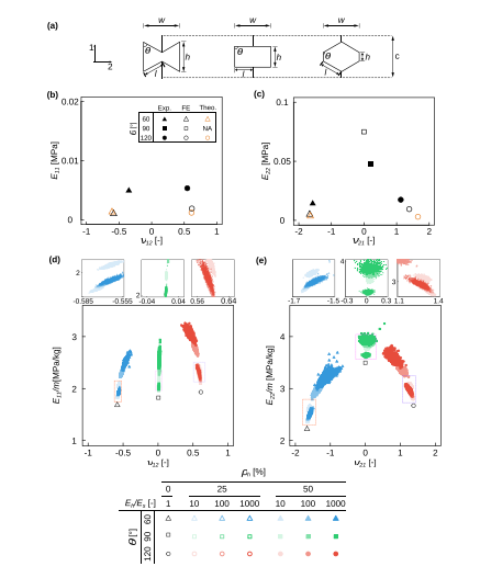
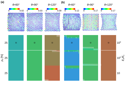
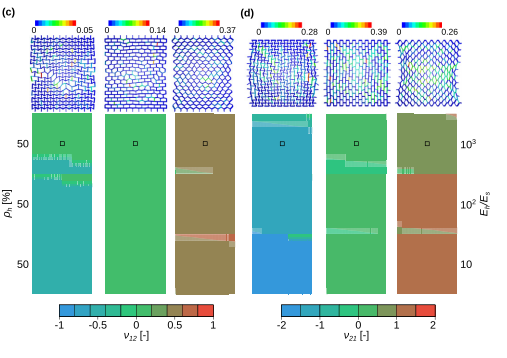
(a) Three unit cell geometries ðh ¼ 60; 90; and 120Þ used for the fabrication of lattice structures. A comparison of the numerical results, experimental observations, and theoretical predictions for the lattice structures made from a uniform (soft) material and tested in directions 1 (b) and 2 (c). The regions covered by the mechanical porperties of multi-material mechanical metamaterials with three geometries and random assigment of a hard phase to the elements of the lattice structure until two fractions of the hard material, qh¼ 25% and 50%, were achieved. Moreover, three different values of Eh Es were used to calculate the elastic modulus and Poisson’s ratio in directions 1 (d) and 2 (e). The specific elastic stiffnesses, i.e., normalized by the mass, m, of the sample are presented in (d) and (e).
Accuracy was confirmed for ‘numerical simulations’ by measuring them against testing models.
“The results of this study clearly show that both random and rational distributions of a hard phase could be used for independent tailoring of the elastic modulus and Poisson’s ratio of a soft mechanical metamaterial,” concluded the researchers.
What do you think of this news? Let us know your thoughts! Join the discussion of this and other 3D printing topics at 3DPrintBoard.com.
[Source / Images: Multi-material 3D printed mechanical metamaterials: Rational design of elastic properties through spatial distribution of hard and soft phases]

The numerical (hollow markers) and experimental (solid markers) results for the elastic properties of multi-material lattice structures with rationally designed hard phases and tested in directions 1 (a) and 2 (b). The arrows compare the results of a corresponding lattice structure with a single soft material with those of the multi-material designs. The experimental and numerical deformation patterns are also compared with each other in directions 1 (c) and 2 (d). The strain distributions show the principal strains obtained using the computational models.
Researchers Decrease Support Structures for Models Through Multidirectional 3D Printing
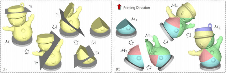
An illustration for the idea of the algorithm: (a) a progressively determined planar clipping results for generating the optimized base planes, and (b) the inverse order of clipping planes results in a sequence of regions to be fabricated where the printing direction of each region is the normal of its base plane. The orientation of a printing head is fixed during the procedure of physical fabrication. The parts under fabrication are reoriented to realize the multidirectional 3D printing.
In most planar-layer based 3D printing systems, material collapse is prevented on large overhangs by adding support structures to the bottom. But support structures in single-material 3D printing methods have some major issues, like material waste and the possibility of surface damage. This can be helped by introducing rotation and turning the hardware into a multidirectional system, where models are subdivided into separate regions and each one is 3D printed along a different direction.

L-R: Snowman models fabricated by an FDM 3D printer and the team’s multidirectional 3D printing system by adding only one rotational axis on the same 3D printer.
A team of researchers from Tsinghua University, TU Delft, and the Chinese University of Hong Kong developed two types of multidirectional 3D printing hardware systems: one modified from an off-the-shelf FDM 3D printer with an added rotational degree-of-freedom (DOF), and the other implemented on an industrial robotic arm to simulate a tilting table for two rotational DOFs. They outlined their work in a paper titled “General Support-Effective Decomposition for Multi-Directional 3D Printing.”
The abstract reads, “We present a method to fabricate general models by multi-directional 3D printing systems, in which different regions of a model are printed along different directions. The core of our method is a support-effective volume decomposition algorithm that targets on minimizing the usage of support-structures for the regions with large overhang. Optimal volume decomposition represented by a sequence of clipping planes is determined by a beam-guided searching algorithm according to manufacturing constraints. Different from existing approaches that need manually assemble 3D printed components into a final model, regions decomposed by our algorithm can be automatically fabricated in a collision-free way on a multi-directional 3D printing system. Our approach is general and can be applied to models with loops and handles. For those models that cannot completely eliminate support for large overhang, an algorithm is developed to generate special supporting structures for multi-directional 3D printing. We developed two different hardware systems to physically verify the effectiveness of our method: a Cartesian-motion based system and an angular-motion based system. A variety of 3D models have been successfully fabricated on these systems.”
The researchers wanted to create a 3D printing system that would be able to “add rotational motion into the material accumulation process” to ensure fewer supports, if any. To do so, they created a general volume decomposition algorithm, which “can be generally applied to models with different shape and topology.”
“Moreover, a support generation algorithm has been developed for multidirectional 3D printing,” the researchers explained. “The techniques developed here can speedup the manufacturing of 3D printed freeform models by saving the time of producing and removing supports.”

Progressive results of fabricating models on 4DOF multidirectional 3D printing system and a 5DOF system realized on a robotic arm.
The research team’s paper made several technical contributions, including their support-effective algorithm, which is based on beam-guided search and can be applied to 3D models with handles and loops. In addition, they also summarized decomposition criteria through their multidirectional 3D printing process and created “a region-projection based method” for generating supports for multidirectional 3D printing.
There are, however, some drawbacks involved when changing from one 3D printing direction to another, such as slowing down the process, which is why the researchers “prefer a solution with less number of components, which can be achieve by considering the following criterion of clipping.”
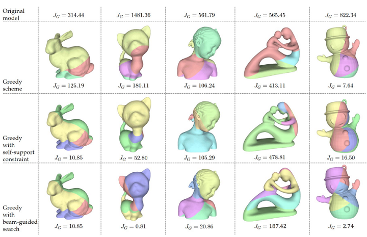
A comparison of decomposition results obtained from three schemes introduced in this paper.
“After relaxing the hard-constraint of support-free into minimizing the area of risky faces as described in JG, the scheme of generating support is considerately vital while both feasibility and reliability should be guaranteed,” the researchers wrote. “To tackle this problem, we propose a new pattern called projected supports that ensures the fabrication of remained overhanging regions through a collision-free multi-directional 3D printing.”
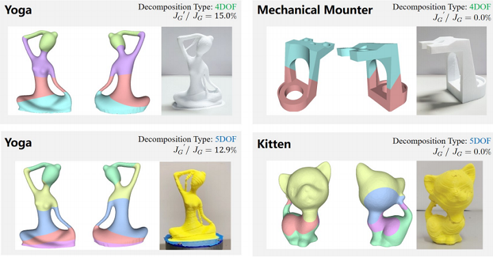
The decomposed and 3D printed results fabricated by the system with 4DOF and 5DOF in motion.
The team applied their algorithm to several models, and were able to reduce, and even eliminate in some cases, the need for support structures. In addition, their method’s “computational efficiency” was on par with general 3D printing time.
“We present a volume decomposition framework for the support-effective fabrication of general models by multidirectional 3D printing,” the researchers concluded. “A beam-guided search is conducted in our approach to avoid local optimum when computing decomposition. Different from prior work relying on a skeletal tree structure, our approach is general and can handle models with multiple loops and handles. Moreover, a support generation scheme has been developed in our framework to enable the fabrication of all models. Manufacturing constrains such as the number of rotational axes can be incorporated during the orientation sampling process. As a result, our algorithm supports both the 4DOF and the 5DOF systems. A variety of models have been tested on our approach as examples. Hareware setups have been developed to take the physical experiments for verifying the effectiveness of our system.”
Co-authors of the paper are Chenming Wu, Chengkai Dai, Guoxin Fang, Yong-Jin Liu, and Charlie C.L. Wang.
Discuss this research and other 3D printing topics at 3DPrintBoard.com or share your thoughts below.
Technical Possibilities for Making 3D Printed Engineering Components Based on Reused Polypropylene
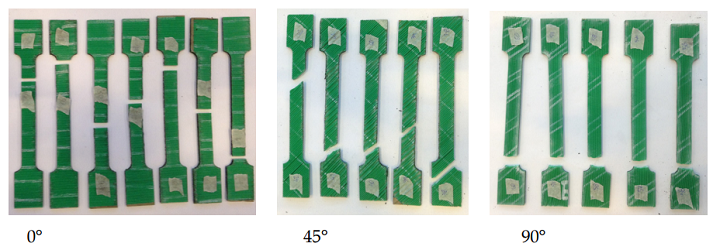
Tested specimens for the three print directions.
From bacteria and metamaterials to shape-shifting and support-free, the innovative researchers at TU Delft have worked with a wide variety of 3D printing materials over the years. Now, their focus is shifting to polypropylene, a thermoplastic polymer used in a variety of applications, though engineering is not typically among these.
TU Delft researchers Fred Veer, Foteini Setaki, and Ton Riemslag, together with P. Sakkas from The New Raw, have published a new paper, titled “The strength and ductility of glass fibre reinforced 3D-printed polypropylene,” that discusses the technical possibilities for making 3D printed engineering components based on reused polypropylene.
The abstract reads, “The possibility of using a mix of recycled polypropylene (PP) with new glass fibre reinforced polypropylene as a materials source for 3D printed engineering components is investigated. The strength and elongation to fracture are determined for various grades of material and in relation to the print direction. The measured values are compared with literature values for these materials in an as new condition. It is shown that the use of recycled PP degrades the material properties. PP recycled from house hold waste has significantly worse properties than PP recycled from industrial waste.”
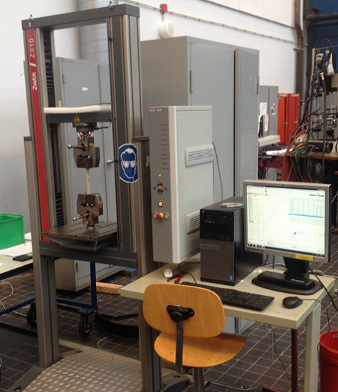
Test setup: Zwick z10 universal testing machine with Test Expert 4.12 software.
A lot of primary material is used to create disposable molds out of virgin plastic for construction purposes, which is not great news from an environmental standpoint. It’s far more practical to use recycled plastics as raw materials, and research has been conducted in the past regarding the use of recycled high density polyethylene. But PP has better mechanical properties, and has the correct thermal properties for 3D printing.
Unfortunately, recycled PP is far less strong than unused PP. In order to achieve the desired properties, recycled PP is often mixed with the virgin material and fibers.
“For this research different mixtures of recycled, re-recycled and virgin polypropylene with short glass fibres were tested to look at the various factors influencing the overall properties,” the team wrote. “This research focussed on the failure strength and strain of the material as these are good indicators for materials performance and are also suitable to compare the different mixtures.”
The researchers blended mixtures of recycled, re-recycled and virgin PP with short glass fibers, then inserted the material into a heated extruder with four chambers to be 3D printed into sheets. The sheets were then laser cut into dog bone-shaped specimens and tested using a Zwick z10 universal testing machine.

“For mixtures 1 and 2 the properties were determined in the print direction, 0°, at 45° to the print direction and at 90° to the print direction,” the researchers explained. “Mixtures 3, 4 and 5 were only tested in the 0° direction in order to allow comparison between the mixtures.”
The results show clearly that the predictability of the strength of a material mixture was degraded by the use of recycling, unfortunately. In addition, it’s implied that the print direction has to be taken into account in any design, and that the structure must be modeled using direction dependent properties. Because we’re dealing with composite materials, the researchers explained that “the engineering effort will be much greater than with conventional materials.”
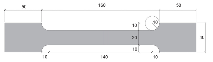
Test specimen; dimensions are in mm.
Another important factor to take into account is the quality of the recycled material: the average of mixture 1’s strength was only about 85% of the average strength of the virgin 10% glass fiber-filled PP homo polymer. There’s also a major decrease in properties – a 35% loss of strength – when a print was recycled. Properties were also significantly degraded when household waste was used as a recycled PP source, as opposed to industrial waste.
“Adding more glass fibres and using less recycled polypropylene gives a mixture that more clearly approaches that of virgin material. An eco-friendly design using large amounts of recycled material will thus always have significantly decreased properties, leading to the use of more material,” the researchers concluded. “In itself this does not have to be a problem, using a larger amount of waste material also means less waste to burn. It is, however, also clear that reusing the material more than once leads to more significant loss of properties as is evident from the loss of properties of mixtures 3 and 4 compared with mixtures 1 and 2. Using recycled polypropylene for products with a short service life is thus counterproductive as it produces unusable waste which can only be burned, as it will not biologically degrade in a land fill. It is thus important to use recycled polypropylene in such a way that a sufficiently long life time is achieved with a clear route for final disposal at the end.”
The team also stated that there appeared to be no clear relation between strain at fracture and failure stress, and determined that properties at 45° or 90° to the print direction are much lower than in the print direction.
Discuss this research and other 3D printing topics at 3DPrintBoard.com or share your thoughts below.
Watch: TU Delft’s morphing chaise lounge proves applications for 4D printed furniture
Exploring the capabilities of 4D printing, members of the Robotic Building (RB) research group at Delft University of Technology (TU Delft) in the Netherlands, have created a 3D printed chaise lounge that can swiftly transform into a bed. Project: Adaptive Stiffness Last year, Henriette Bier, TU Delft Associate Professor, and RB Group Leader and Arwin […]
TU Delft: 3D Printed Chaise Lounge Morphs into a Bed
 Netherlands-based Delft University of Technology (TU Delft) is one of the world’s leading higher learning institutions, evidenced by continual innovations in student research. We have followed as TU Delft faculty have 3D printed electronic devices, students have fabricated parts for racecars, and even performed studies regarding some pretty amazing potential for 3D printed bacteria and its uses in space; however, student research at TU Delft also seems to have a recent and strong focus on delving into the 4D, giving us a glimpse into the future as we move even beyond the third dimension and look forward to objects that can adapt and morph—depending on the needs of their users.
No strangers to the world of soft robotics, 3D printed shape-shifting assemblies, as well as the fabrication of a variety of metamaterials, researchers have now set their sights on 3D printed pieces that could change the way furniture is designed and manufactured in the future. Arwin Hidding is a student at TU Delft, centering around current work with the Robotic Building research group. After finishing his master’s degree in architecture (and just before embarking on his PhD in 3D printed architecture), Hidding began working on a design for an innovative chaise lounge that sounds as if it could spoil consumers forever in terms of features and comfort.
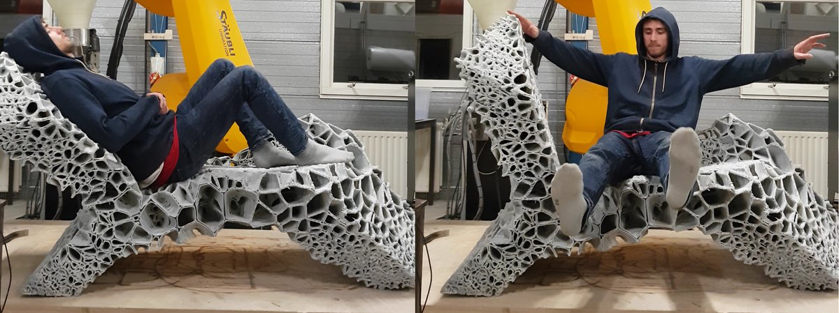
Transforming from a lounge chair into a bed within mere seconds, this 3D printed piece is all about giving the user what they require in the moment—whether they want to sit and relax—or lie down, activating movement as they lean against the rear of the chaise.

“In the past, furniture could only take on a different shape in cartoons. 3D robot printing, variable stiffness, and adaptive structures were unheard of at the time,” Hidding told 3DPrint.com.
“The aim of the project was to develop a 3D printable pattern that would allow control over the stiffness over the material. Variable stiffness is employed in this project as an adaptation strategy to achieve multi-functionality.”
Using growing expertise in the field of both 3D printing and architecture, Hidding and a team of TU Delft researchers experimented with the concept of shape-shifting furniture. Along with progressive design concepts, they relied on intricate structural analysis, robotic path simulations, and 3D robotic printing for creating the ‘adaptive structure.’ The design is meant to support an average-sized human, with the morphing mechanism activated by their weight on the back of the structure.
“This shape change is achieved by combining variation in material distribution and use of thermoplastic elastomers,” Hidding told 3DPrint.com.
Other project members from TU Delft included Henriette Bier, Patrick Teuffel, Qing Wang, and Senatore Gennaro. The 3D printed chaise lounge is slated to be on display for the public at the Dutch Design Week from 20-28 of October in Eindhoven. Find out more about this project and other Robotic Building projects here.
What do you think of this news? Let us know your thoughts! Join the discussion of this and other 3D printing topics at 3DPrintBoard.com.